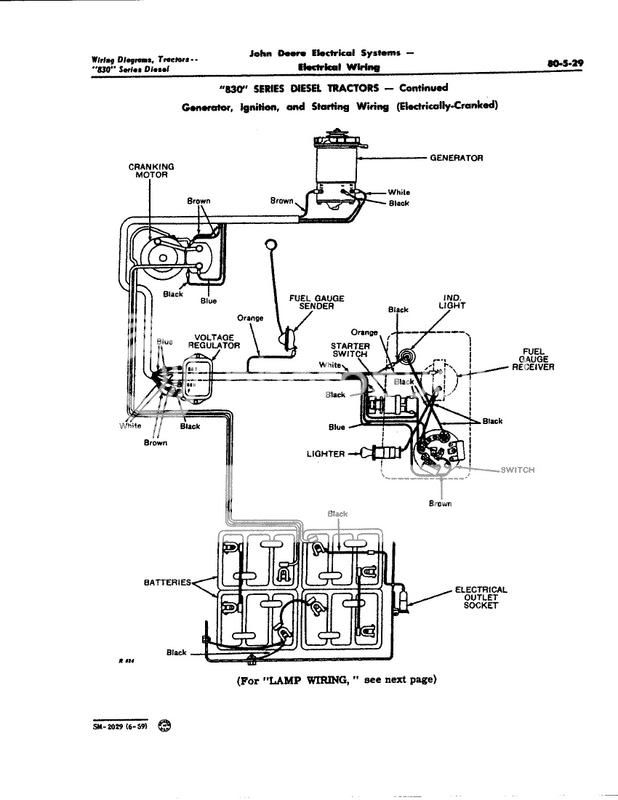
Battery Hook UP ( Ben Donovan)

BEN take my advice that so called ground wire that they are looking at is the 12 volt hot wire for the lights. Hook it to ground and Poof.
Walt
 
Wally,

You're "outgunned" here.

Deere electrical GURU JohnT, JMOR, and myself gave him the "straight dope". I don't claim any special knowledge, but I've owned about a half-dozen DEERE's with the split 24 Volt system and can troubleshoot them from memory, without even the need for a diagram.

WHAT is your experience with them? Let's hear about it! WHY do you persist in arguing about how DEERE designed them when you are (as usual) CLUELESS?

Give it up and take a heart pill, Richard Edward!
 
Ben, This isnt really rocket science guys, below is a wiring diagram from Service Manual 2029 A JOHN DEERE PUBLICATION IT IS NOTTTTTTTTTT MY OPINION OR DIAGRAM.

As it shows the mid center tie point of the series connection (two 12's or four 6's) IS BONDED TO FRAME GROUND. The reason why is so there exists TWO 12 volt circuits (to light switch, the A & B circuit feeds) for lights etc WITH RESPECT TO FRAME GROUND. One circuit is Pos ground the other is Neg ground. YES the remote electrical socket is connected to ONE of the batteries as shown and that is part of ONE of the 12 volt TO GROUND circuits that could furnish 12 volts to say a remote device or an implement or light etc.

ITS TRUE YOU DO NOT GROUND EITHER OF THE BATTERIES AT THEIR OUTERMOST UNTIED POST (ONLY at the mid center junction as shown) because that would indeed create a dead short to ground across that particualr battery and GO POOF AS WALT MENTIONED !!!!!!!!!!!!!!!!!!!! The bond to frame is ONLY at the mid center junction as shown and for the reasons I gave

Im NOT here to fight ONLY to help others and Im showing and describing how John Deere wired the system originally and trying to explain why they did so but hey its your tractor and you can wire it any way you see please.....

Yall take care now

John T
830-D-2-JPEG.jpg

830 Wiring Diagram
 
I'm no mechanic and I can't remember how many of the 24V John Deeres we've owned, but there are still 3 of 'em still here. They were/are wired exactly as been discussed. If I wasn't so lazy and it wasn't so foggy outside, I'd go take a picture and post it.
 
Well, in a way, it might as well been "rocket science." That split system confused a lot of people, including some tech guys at Deere Co. We were sent to winter service schools ad nauseum for many years because of all the problems associated with the system (functional and service related). I spoke with a few Deere instructors who did not even understand what they were teaching. I suspect part of the problem was that Deere Co. did not design it (they hired out for the unique design). I still don't understand why they didn't just use a conventional 24 volt system like Allis Charmers did. A groundless isolated starter is near impossible to keep isolated. Brush dust screws it up and creates a path to ground.

As to factory wiring diagrams - they certainly reflect what was used at that time of production, and may or may not reflect changes made later. Last Deere place I worked at, we had Deere tech bulletins stuffed in many of the original books for tractors with 12-12-24 systems. Especailly the 3020s and 4020s.

I have to confess though, we never had a two cylinder diesel in our shop any larger than a 720. No 820s twos around here in my part of NY. 820 fours, yes.
 
The military used the conventional 24 volt system and even though I retired over 20 yeras ago I think its still being used. If we needed 12 volts for some of the instumentation it was available too. Hal
 
My Allis Chalmers HD6 has a nice conventional 24 volt system. No funny stuff involved.

I know the military CUCVs that use General Motors 6.2 or 6.5 diesels use an oddball 12/24 volt system. Uses dual 12 volt alternators and some s special relays to make 12 or 24 volts when and where needed.
 
I was asked to give a 24 volt Seminar at a couple of the JD shows I attend but resisted it big time, they finally talked Tom into giving it and I attened but most attendees had that deer in the headlights look lol. One problem is the old wires are faded so theres no longer much use in trying to use a color coded diagram. Also theres so many wires crammed under the dash around that switch its just tough (even if you knew what you were doing) to trace and troubleshoot things.

Seems some semi trucks used a series/paralell switch relay system so they could put 24 volts to the starter and then all was back to 12 volts. Years ago I used to buy combination 6/12 volt batteries with a series paralell relay in the middle so the vehicles started on 12 then ran on 6 volts. EITHER of those may be easier to understand then Deeres 24/12

Fun discussion but likely not much help to many here.

John T
 
If you hooked either outermost untied battery post (+ on one - on the other) it goes POOF (even for a good non shorted starter) because thats a direct short across that battery (as its other end is tied to frame ground). When copper brush particles/residue inside a starter creates a path to frame ground it dishcharges the battery.

John T
 
It won't go poof because neither the pos or neg of the 24v leads are attached to the frame. They both terminate at the starter. On on the solenoid, the other at a special terminal on the starter itself. To get 12v to run lights, fuel gauge, and other accessories you need to center tap the batteries to a chassis ground.

Look at JohnT's schematic, one battery lead is attached to the solenoid, the other is attached toward the top of the starter to a special terminal. This terminal is isolated from the chassis and is connected directly to the windings of the starter.

The generator is a split 24v also. The 24v splits into 12+ and 12- with a center chassis ground. So each batt gets its own 12v and gets charged individually. This balances the batts so one doesn't cook while the other is still under charged.

On my 4020 half of the lights are powered by 12+ and the other 12- (there are two power terminals on the switch)this also helps balance the system
 
Our military is still using the series/parallel relays on some rigs. As I recall, Deere also did it on a few tractors.
 
Actually, assuming the mid tie point of the batteries is grounded to frame as shown on the diagam, IF YOU ATTACH EITHER OF THOSE BIG CABLES (one to solenoid other to starter) TO FRAME GROUND SOMETHING WILL INDEED GO POOF as youre placing a 12 volt battery across a dead short. Often it will be that small bonding wire to frame that will burn open

YES the starter is isolated from ground, its windings are between its 2 big stud/terminals AND ARE NOT BONDED TO CASE FRAME as so on a typical 12 volt starter where the starter has one stud and its case frame is the other terminal

Think about it.....ONE end of a battery is tied to case/frame there at the mid point as the drawing shows.......Soooooooo if you also atatched the other end of that battery to frame WHY DO YOU THINK IT WILL NOTTTTTTTT CAUSE A SHORT/POOF. YES the starter windings are isolated from case BUT TRUST ME IF YOU TOUCHED EITHER OF THOSE BIG CABLES TO CASE FRAME SPARKS WILL FLYYYYYYYYYYYY.....

Again this subject is just too complicated to explain here on the net in a few paragraphs and yall can wire as you like but if that mid tied point is correctly bonded as Deere did which is correct PLEASE DO NOT TOUCH EITHER OF THE 2 BIG CABLES TO FRAME FOR YOUR OWN SAFETY. If the mid tie point isnt correct and isnt grounded or has burned open she will NOT go poof

Yall take care now n be safe and wire them as you please I just dont want anyone to get hurt by dead shorting a battery based on something read here BETTER SAFE THEN SORRY I SAY

John T
 
(quoted from post at 14:37:32 01/18/10) I was and still am agreeing with you. If everything is correct, big leads to their terminals and center tap 12v chassis grounded. All good. Something goes wrong then the smoke is let out.

"Something goes wrong then the smoke is let out." Isn't that always the case with anything electrical?

On another point, however, we likely have a bone to pick. I see nothing to suggest that the following is an accurate description:

The generator is a split 24v also. The 24v splits into 12+ and 12- with a center chassis ground. So each batt gets its own 12v and gets charged individually. This balances the batts so one doesn't cook while the other is still under charged.

I believe that the charging is a simple matter of batteries being charged by a single, non-split, 24volt gen/reg where the current is the same thru the series of batteries, with no provision to yield any more or any less charging to one battery than the other, even if one should be more discharged than the other. That generator is just like the starter in that it knows of no ground and that regulator only knows of 24 volts and knows of no ground and thus knows of no +12 and -12.

I could be wrong, but so far see no evidence to support that position.
 
Well its about time someone explained how this all works. When it was first explained you had 4 six volts in series. No one said anything about a 24V starter that is not grounded. When you leave one little part out like that you just cause problems.

If I had know about the non-grounded 24V starter I would have agreed with you but as usual no one said anything about that.

Next time you put up a diagram make sure that's what it is. What you showed is a Wiring layout which is lacking a few things like where the grounds are and how the batteries are laid out. You will notice that there is no markings as to what posts are what on the batteries.
So look at this wiring layout and tell me if its a Positive or negative system.

Walt

PS next time get a real diagram and tell the whole story and don't leave out a few very important details just because you know them doesn't mean that others do.
 
I agree with you . Also I believe the regulator is mounted on rubber insulators & not grounded to chassis. It has been years since I have worked on that system.
 
I never had a chance to work on a 24V 2 cyl, but worked on many of the new generation 4 and 6 cyl tractors. It was a cheap way to make a 12V / 24V combination system, but it did not work very well, especially as it aged.

As the starter wore a bit, it's innards got a coating of conductive brush dust, and those internals were electrically hot to chassis ground 24 hours a day.

That would put a constant slow drain on whichever battery that was connected to the starter case terminal next to the engine block.
If the tractor sat unused for a few days, that battery would be partially discharged while the other one was still at full charge.
When you started the tractor, the charging system would immediatly start recharging the low battery with the full one hooked in series with it. This lead to short battery life, as one was constantly having it's fully charged guts boiled to death, while the other one was always low and being ruined by sulphation. Having to replace both batteries every 1-2 years was normal, more often every year.

In our dryland prairie state, where wheat was king, the most cost effective way to a low cost, high capacity wheat harvest was using a pull type, PTO driven combine. With those combines being PTO driven, they had no engine or self contained electrical system, they pulled electrical power from the tractor.

Harvest was when the electrical thing got really ugly for the 24V JD new generation diesel tractors.
The most popular combines of the day were the IH 914 and the JD 6601 windrow machines.
Both needed aprox 15-20 amps at 12V to power the bank of work lights and the big magnetic clutches that started / stopped the feeder and unload systems.
The electrical supply for those combines had to be tied to one battery of the 24V JD.
You could not wire a SPDT switch to to alternate this 12V electrical load from one battery to the other as the harvest day wore on, because the magnetic clutches on the combine had a diode wired across the leads to absorb that big voltage spike generated when you switched off power to that clutch. switching to that other battery with it's opposite ground wiring would cause a dead short across the diode that would instantly blow the fuse. ( atleast you hoped it blew the fuse instead of the diode.)

With the average day of the combine pulling power from that battery all day and several hours into the night with all the lights on, you could be nearly certain of one thing the next morning, the combine had sucked one battery dead and the 4020 would not start. The most common crutch if the tractor / combine had to stay in the field, was to lock the header in the raised position and park the tractor / combine where you could pull start it with another tractor the next day. After a month of this, the one battery was overcharged to death and the other was terminally near dead and sulphated. New batteries were usually required to get the tractor reliable starting for fall tillage work.

When JD finally got over that PITA 24V system and switched to a chassis ground 12V system in 69 ? All those problems went away.

I would estimate that 95% of the pre 69 new generaton diesel's have been converted to 12V and are far better for it. 12V loads are no longer a problem and batteries average a half dozen years life.
About the only 24V tractors left in the area, are the ones used strictly as a loader tractor in winter, and do start a bit better.

The most sucessfull, remove the starter yearly for a cleaning to remove brush dust and /or a rebuild. You need to keep the generator and starter free of brush dust to eliminate the parasitic deain on that one battery, and never ever let that fiber thrust washer at the commutator end of the starter wear out.
If that washer wears too thin, the commutator bars touch the starter end cap and put a dead short on one battery. The moment this washer wears too thin is when the little jumper wire DOES go poof !! Most have a fuse or automatic reset breaker inline to protect that wire. When that wire burns off, you lose headlights, oil light and fuel guage.
 
NOTHING to explain you dumazz...

He said it was a 2 cylinder DEERE diesel. Simple, if you don't know what that is, just lay by your dish!
 

Walterdavies
John T and the others have explained a 24V system very correctly and the wiring diagram is correct for a 2 cyl D. Just because Ben wanted to replace four 6V batt. with two 12V batteries doesn't change anything as a factory wiring diagram with two 12V is unavailable.

GIVE IT UP
 

We sell tractor parts! We have the parts you need to repair your tractor - the right parts. Our low prices and years of research make us your best choice when you need parts. Shop Online Today.

Back
Top