Battery Charger Experts .... need help !!

Crazy Horse

Well-known Member
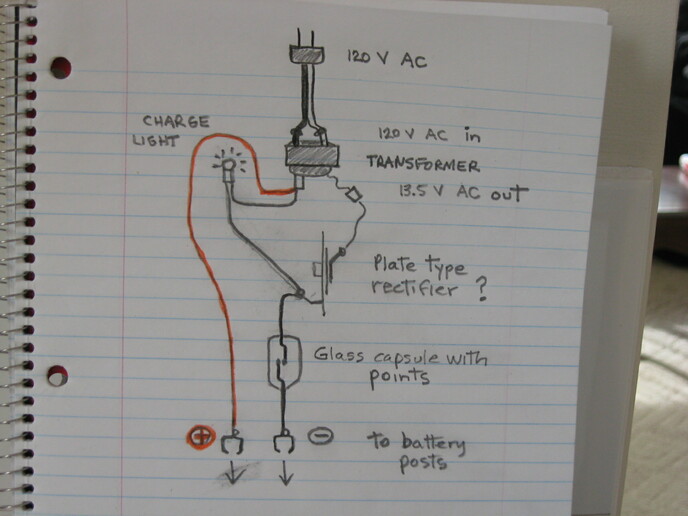
Well, I need help, hopefully those in the know can help me. I have an older 12 Volt 2 amp charger that only kicks out about 0.5 volts DC when measured at the output clips.. There is no charging rate meter gauge on this charger but there is a little light (which I call a charging light but maybe it's a polarity check light, not sure). See the diagram below and my description of what's there follows.

From top to bottom in my diagram ..... I have a 120 Volt AC input (household) which hooks up to a step-down transformer. I think that's the correct term. When plugged into house current by itself (not tied into the charger wiring), the transformer shows 13.6 Volts AC coming out of it so it appears to be working. I think the rest of the diagram is self explanatory.

Some other things ........ I believe it is a 'plate-type rectifier' I labelled that is supposed to covert the 13.6 V AC current to DC current right? Then there is that little glass capsule with a set of points inside (currently closed), maybe some kind of a charge limit control or something like that? Or safety shut off? I have current continuity through the rectifier. Once this is all hooked up and plugged in, I have only checked the DC volt output at the clips that hook up to the battery (and got that tiny reading).

So a simple question and maybe a simple answer. Any ideas as to what is wrong here or not working? Or what I need to test further or do to put this charger to use?

PS: I did a little test thinking that maybe the battery charger only kicks out full charge when hooking up to a 12V battery. I tested a battery by itself and it read 12.4 volts. I then hooked up the charger to the battery and plugged it in. The DC reading at the battery posts remained unchanged at 12.4 volts so the charger appears not to be having any effect when hooked up. I guess my volt meter is just reading the existing battery voltage when I do that.
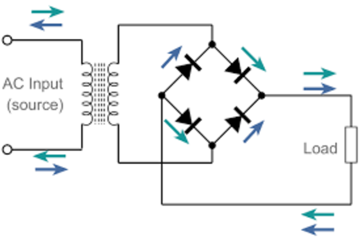

cvphoto119985.jpg
 
Crazy Horse,

Not an expert at anything. I like your pictorial.

I think what I see is a half-wave rectifier. I am unsure of your meter, some digital meters do odd things when they do not have a symmetrical AC sine wave. That may affect your reading(s).

Also, you mentioned current continuity across the plate. Did you try this de-energized with the wire removed from the diode (plate), and with your leads hooked up one way, then switch the lead polarity? continuity should read one way, not the other.

I think the glass capsule is probably not the issue. I suspect the rectifier (diode). I hope you find the problem,

D.
 
Thanks for the reply Dennis. I did what you said, disconnected all wires to the rectifier (or diode or whatever). It reads to be carrying current in both directions so it has continuity no matter how you hook up the meter. So that sounds like it's not working then, is that right?

It's not much of a device for complexity, just two metal plates, one stacked on top of the other, one is bigger (about1.5 square) and the other one smaller, about 0.5 square. Each one has it's own electrical tab for connecting wires, one for each plate.

So I just did another test with everything hooked up. I plugged the charger into the wall outlet and guess what? The battery charge leads (+ and -) show 13.6 volts but AC, not DC. Funny I never checked for that before assuming that it would only be DC currecnt. So it would appear that I am reading the AC current which is leaving the transformer and it is not being flipped to DC current.

Looking around on the web I see thousands of what they call bridge rectifiers of all sorts, sizes, and specs. Not sure if this is what I need or not, the plate type seems to be a bit dated from what I read. I wonder how those two simple plates are able to flip AC to DC if working properly, it looks like something a kid could make up with some tin, a center rivet an some electrical tabs.
 
(quoted from post at 16:13:05 03/13/22) Thanks for the reply Dennis. I did what you said, disconnected all wires to the rectifier (or diode or whatever). It reads to be carrying current in both directions so it has continuity no matter how you hook up the meter. So that sounds like it's not working then, is that right?

It's not much of a device for complexity, just two metal plates, one stacked on top of the other, one is bigger (about1.5 square) and the other one smaller, about 0.5 square. Each one has it's own electrical tab for connecting wires, one for each plate.

So I just did another test with everything hooked up. I plugged the charger into the wall outlet and guess what? The battery charge leads (+ and -) show 13.6 volts but AC, not DC. Funny I never checked for that before assuming that it would only be DC currecnt. So it would appear that I am reading the AC current which is leaving the transformer and it is not being flipped to DC current.

Looking around on the web I see thousands of what they call bridge rectifiers of all sorts, sizes, and specs. Not sure if this is what I need or not, the plate type seems to be a bit dated from what I read. I wonder how those two simple plates are able to flip AC to DC if working properly, it looks like something a kid could make up with some tin, a center rivet an some electrical tabs.
t is the chemical/compounds on the plates (selenium, etc.) that make it a rectifier/diode. A bridge rectifier has 4 diodes. You only need one diode, but a bridge can be wired so as to use only one of the four. These are all diodes, from a fraction of an ampere to 100 amperes.
RTfHPr6.jpg
You select one that fits your current and voltage needs. Maybe 50v and 4-5 amperes.

This post was edited by JMOR on 03/13/2022 at 01:50 pm.
 
A diode rated for 4 amps or more and PIV ov40-50 volts should work. But pay attention to the polarity of the diode. If put it in backwards the + and - terminals will be reversed.
 
Crazy Horse,

A simple 1/2 rectifier circuit. Replace the plate with a single rectifier of the proper size. Having the charger hooked up is the key to troubleshooting.

A charger will almost never charge the rated amps. I say almost never with reservation, charge rate is predicated by the battery resistance and state of charge.

In other words your 2 amp charger, even if its a manual charger, will diminish the charging rate, as the battery voltage comes up,

Guido.
 
JMor ..... Thanks for the info. I think I follow you. Looks like my plate rectifier (or diode or whatever you want to call it) isn't working, at least I'm assuming it isn't.

I hunted down a set of instructions on the web for making (from scratch) a simple battery charger. The little project I saw used what the writer called a 4 amp bridge rectifier, they didn't mention the voltage. Four wires were attached to the rectifier, two in and two out. The 2 in would attach to the output of the transformer (AC volts) .... in my case 13.6 AC volts. Then leading out of the rectifier are two wires, one would hook to a (+) lead to the battery, the other to a (-) lead to the battery. Make sense? Is that a simple way of doing it?
 
Crazy Horse,

I agree with your assessment.

The diode conducts (both ways) is a giveaway that it has failed. The AC at your charger output cements that idea.

The other recommendations of getting a diode (single) rated for a few amps and the 50v PIV rating would work. You most likely do not need a bridge network, seeing as your charger did what you wanted it to.

You done good, especially the drawing. Makes it easier to lend some assistance.

D,
 
Thanks JAN ..... so in the link you posted, the little bridge rectifier replaces my plate-type unit. Two wires from my transformer's output side (13.6 AC VOLTS) into the rectifier. And then the two wires out connected to the red and black wires with clips to hook up to the battery posts.

Is that the spec you would recommend (200 V & 30 amp) or just what the spec was on the link you posted?
 
Dennis is right, that is a very nice drawing! That glass capsule appears to be an overload breaker; thats basically where a conventional breaker would be located in other chargers. Did you check the voltage on the up-stream side of it, to see if the points are making poor contact. Another possibility is corrosion where the wires attach to the rectifier, or wherever wires are riveted to something else.
 
I think what you have originally (plate type rectifier) is a selenium rectifier. It is a half wave rectifier made with plates coated with selenium and copper and other stuff of which I forget. Lets current flow in one direction only. They came out towards the end of vacuum tube rectifiers. A decent diode can replace it but check polarity on your output before hooking up to a battery.
 
Yes. My only thought is that it could double the output by using both halves of the incoming cycle. a single diode (shown in another post on here or removed from a old alternator output bridge) would also work. Jim
 
Jannicholson,

I believe you are spot on....I was trying to dig from memory the peak-to-peak voltages, effective voltages, etc. ( twice the waves most likely is twice the dc equivalent) or something like that.

I think his simple way out would be a single replacement diode.

D.
 
JMOR ..... reading your reply again and then someone else who referred to your post & photo, just one of these kinds of diodes in your photo would work (to replace the plate-type rectifier that I have now or a bridge rectifier) .... is that right? So just wire it into the same space with the same wire in (from the transformer) and wires out (one to the charge light circuit and the other to the negative battery clip) in my diagram, and it should work?

What type of application are these diodes used for in everyday life now? I'm just wondering where a guy looks to find what I would be looking for?
 
(quoted from post at 08:56:12 03/14/22) JMOR ..... reading your reply again and then someone else who referred to your post & photo, just one of these kinds of diodes in your photo would work (to replace the plate-type rectifier that I have now or a bridge rectifier) .... is that right? So just wire it into the same space with the same wire in (from the transformer) and wires out (one to the charge light circuit and the other to the negative battery clip) in my diagram, and it should work?

What type of application are these diodes used for in everyday life now? I'm just wondering where a guy looks to find what I would be looking for?
es to both questions. Rectifiers are in virtually all electronic devices. I last week cut several out of a non working satellite receiver before tossing it into recycling. The higher capacity diodes are in the power supply section of appliances. Electronics supply businesses, electronic hobby shops, etc are sources. I don't recommend the bridge, as that will alter both current and voltage of your charger & very likely overload the transformer. This drawing shows how you could utilize only one of the 4 diodes in a bridge and have 3 spares. :) To keep = & - correct, the connections to anode and cathode ends of diode are important. I haven;t had my hands on a selenium rectified in 60-70 years, so I can't tell you which connection is cathode vs anode. Maybe someone else will chime in or DuckDuckGO? Silicon diode has band on cathode and in drawings/schematics, it is the end where point intersects the bar/line . In this drawing, it is the end where the arrow head is near each diode.
DAarnWY.jpg
 
I think I got it figured out JMOR, so a guy uses just one of the 4 diodes inside the bridge rectifier, OR one could simply find a diode like the ones in the photo you posted, thanks for the help.
 
Look it up in text book or simply attach DC voltmeter, the DC volts out with a full wave bridge is twice that of a half wave rectified waveform. Peak is same, rms is 1.4 times larger. ....and there is no call to debate heating values, meter types, etc. In his battery charger changing from half wave to full wave is not a good plan....end of story.
 

We sell tractor parts! We have the parts you need to repair your tractor - the right parts. Our low prices and years of research make us your best choice when you need parts. Shop Online Today.

Back
Top