I need an inspection of my electrical work I've done so far. Are wires on the terminal block where they are suppose to be? My electrical knowledge is fairly limited. Does the terminal block just makes a juction point for each polarity..(hot wires and ground wires)? I have a new 12v Cole Hersee ignition pilot light. I hooked the ground of the battery and noticed the light is on constant without the turn of the key. Do I need to rewire this to make it a switched power?
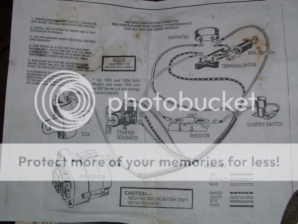
The white wire is the ignition coil. yellow on seleniod runs to the ignition starter button switch. Yellow to Red is hot wire for lights. last yellow is ignition hot wire. One red wire is alternator, and the other runs from the starter selenoid (hot) to ammetter, which i don't have, so I ran it to the terminal block. Orange must be another ground wire from the selenoid? Are the ignition key wires okay? The back of the fuel gauge, has ground connection on the bottom (which goes to the fuel sending unit, I think). Is B for battery? What is T? And is the black part a light for guage?
The white wire is the ignition coil. yellow on seleniod runs to the ignition starter button switch. Yellow to Red is hot wire for lights. last yellow is ignition hot wire. One red wire is alternator, and the other runs from the starter selenoid (hot) to ammetter, which i don't have, so I ran it to the terminal block. Orange must be another ground wire from the selenoid? Are the ignition key wires okay? The back of the fuel gauge, has ground connection on the bottom (which goes to the fuel sending unit, I think). Is B for battery? What is T? And is the black part a light for guage?